| LabGuy's World:
Cartrivision Restoration Project
This page is a continuation of the Cartrivision Museum page and contains the running log of my progress in making this old VCR operate again. As I go along and discover interesting technical facts about the Cartrivision VCR, I will share them with you here. Perhaps you will find electronics of this vintage as fascinating as I do. This recorder was designed at the time that the transistor was beginning to dominate over vacuum tube technology. Follow along if you like. Be sure to bookmark this page and check back every day or two. Don't forget to press your REFRESH or RELOAD button! [CLICK HERE] to return to the previous page. New Additions! 03.05.18 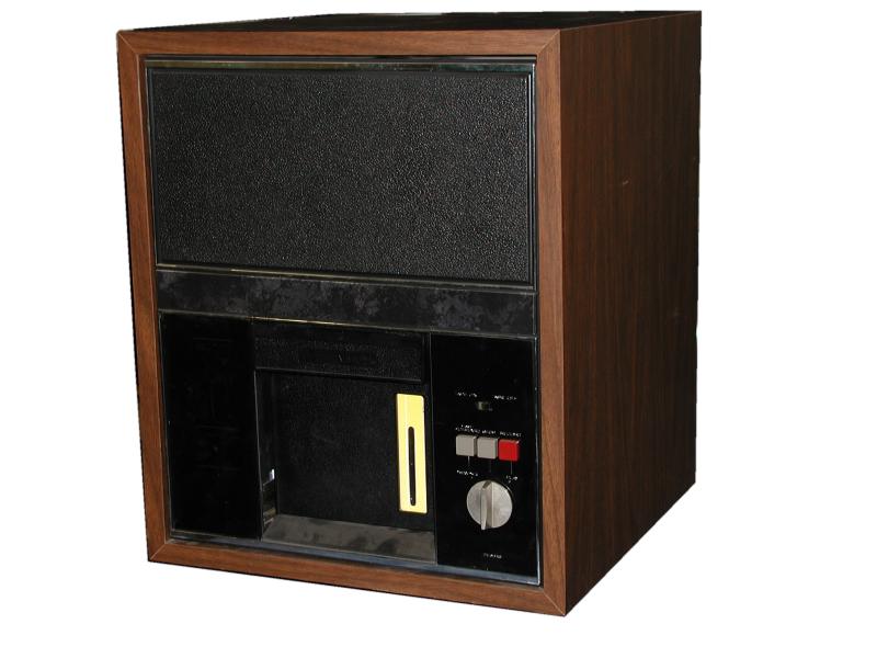 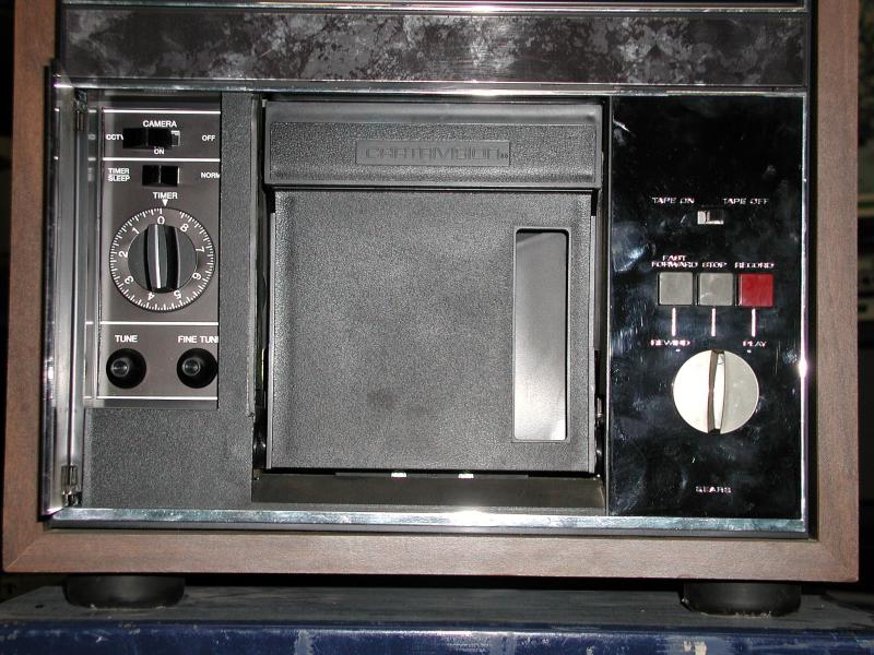 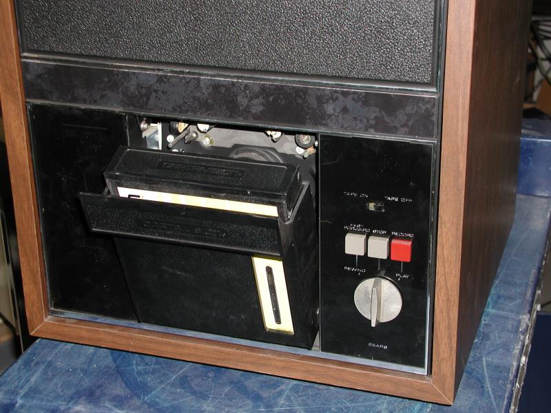
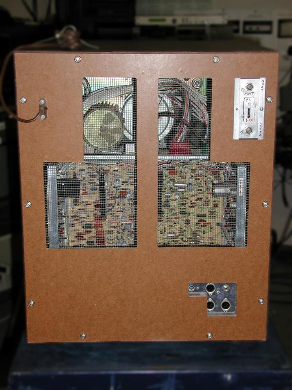 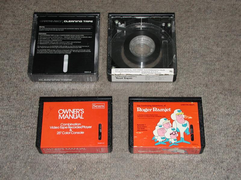 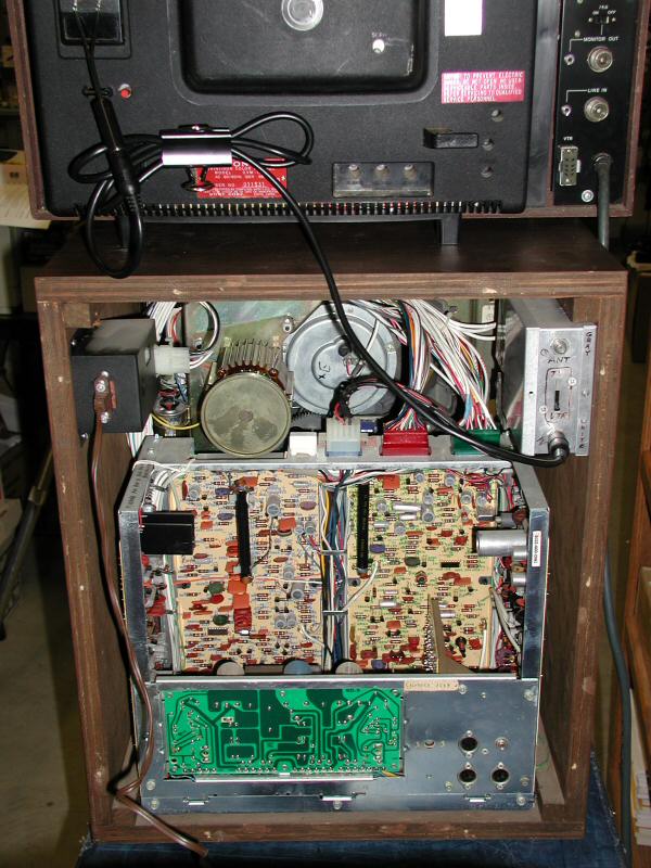
A complete Cartrivision VCR and special tape cartridges Here is the complete standalone VCR unit from 1972. This was obtained from a former employee of Cartrivision. Almost all of the equipment shown on this page came from this source. He has kept several complete machines, tape rewinder machines, dozens of tapes, spare parts and literally tons of documentation. All of it has been donated to LabGuy's World! Thank you, Larry! More information and photos will be posted as I go through it all and sort it out. There must be fifty pounds of documentation alone! At a glance, I have seen several service manuals, engineering bulletins, movie title lists and catalogs, OEM applications information, etc.! The first photo above is of the minimalist cabinet. Only 25 of these cabinets were made. Front panel plastic is original Cartrivision styling. Second photo is a close up shot of the business end of the VCR. Cassette door in the center, timer and mode select controls on the left and VCR operations on the right. Third photo shows a generic blank tape in the loading position just prior to insertion. The fourth photo shows the fiberboard and screen backing which was typical on televisions of the time. This backboard also contains an attached AC power cord. Removing the back disconnected power from the cabinet for safety. In the upper right corner, rear view, you can see the antenna selector switch on the Motorola RF modulator which was added in order to show this deck at the CES show in 1972. The fifth photo shows four examples of Cartrivision videocassettes or cartridges as they were called then. Notice that there are two sizes! the larger cartridges could hold up to two hours of tape. The smaller tapes had a 30 (45?) minute capacity. The cassette in the upper left is a cleaning tape, still wrapped in original cellophane! The tape on upper right is a factory alignment tape with a clear cover so that tape motion could be observed. Lower left is the Sears Cartrivision TV/VCR combo instruction manual on video. Bottom left is one of LabGuy's favorite cartoons! The sixth photo shows the electronics bay, commonly called a "fish tank" because of its size and shape. The fish tank contains 99% of the electronics for the Cartrivision VCR. In the upper left is the AC entry module which uses a two wire "cheater cord" common at that time. In the upper right, is an after market RF converter made by Motorola. It was (probably) hideously expensive in 1972. RF converters were very novel at the time. Today, they are considered commodity items and sell for a few cents each. The green circuit board contains the DC power supply. The main motor with its under rated cooling fan is visible along the top edge of the fish tank. That's my Sony color monitor resting on top of it all. This deck is in excellent condition and may even be operational. I will only put power to this after consulting with some other vintage electronics collectors for advice on bringing up the AC power very slowly in order to reform the electrolytic capacitors. It would be a shame to throw the on switch only to hear a loud BANG! Stay tuned! Update! 03.06.07 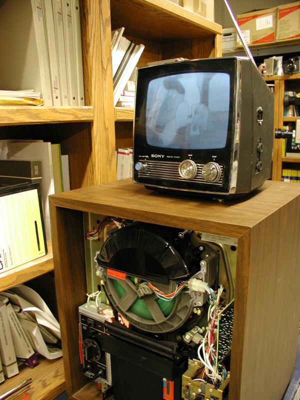 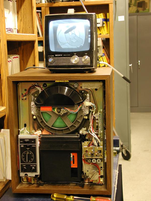
First Pictures from my Cartrivision VCR June 7. Progress is always a good thing! And I love reporting good news. Look at that circuit board spin! The video head amplifier circuits are mounted on the rotating structure that supports them. The entire wheel is spinning at a leisurely 20 revolutions per second. Prior to this, the VCR would spin its heads, but would not thread the tape. After I discovered the capstan drive belt had jumped off the flywheel, it was a simple matter to replace it. Power from the capstan is "borrowed" to perform the thread / unthread operation. Now, the machine plays, though not well. It will make pictures and sound, goes in fast forward, but it will not rewind. I had to stop when all available test tapes had played to the end. <grumble!> The capstan belt is made of mylar and is in very good condition. The secondary drive belt is rubber and it is stretched out pretty good. I believe now there is not enough torque being transferred to the reel hubs to pull against the high back tension exerted during the rewind. That's my theory and I'm sticking to it! After I got to the point shown in the photos, I switched over to a color monitor, but could not get the picture to lock up. The BW monitor has a horizontal hold control and I was able to get a soft-ish kind of lock. This just means that the head motor is running off speed. After the rewind issue is resolved, I will go through perform an electronics alignment. After all these years, it is obviously overdue. Will study the drive system some more and then get to work on that. All progress will be reported here, so book mark this page, Cartridge Television Fans! As usual, stay tuned. . Update! 03.06.12 I have been informed by Larry Fritz that the rental tape rewinder will rewind my tapes! This is very good news indeed! 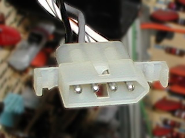 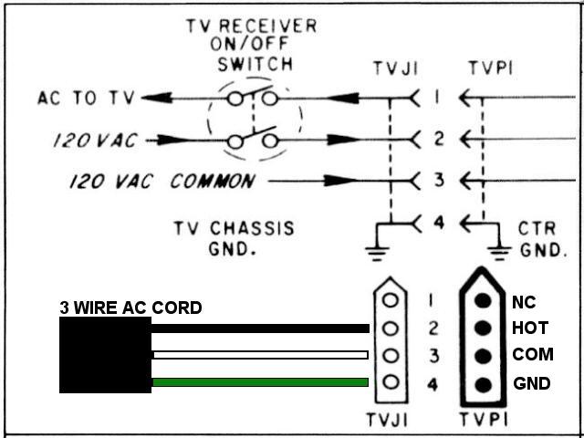
TVP1, THE AC POWER CONNECTOR This is a partial schematic of the Cartrivision AC power connector that is attached to the VCR mechanism. In the photo, pin #1 is on the right hand side. Connecting AC power to the Cartrivision VCR is not difficult. All Cartrivision VCRs are intended to operate from 120 VAC, 60Hz. Start with a regular 3 conductor AC power cord, like the one used on your computer. Cut off the female end and strip the outer jacket back, exposing a couple of inches of the inner three wires. Connect them to TVP1 in the following order: . Connect nothing to pin 1. Connect the BLACK wire to pin 2 of TVP1. (AC HOT) Connect the WHITE wire to pin 3 of TVP1. (AC COMMON) Connect the GREEN wire to pin 4 of TVP1. (Earth GROUND) . You may solder directly to the pins, or cut off the Molex plug and splice your wires together directly. In either case, insulate the connections well with good quality electrician's tape or, better yet, heat shrink tubing. Secure the AC cord to the tape drive with a couple of nylon tie wraps to prevent accidentally pulling out the wires. . ALWAYS CONSIDER SAFETY FIRST! ALWAYS UNPLUG ALL POWER CONNECTIONS BEFORE SERVICING ANY PIECE OF ELECTRICAL EQUIPMENT. 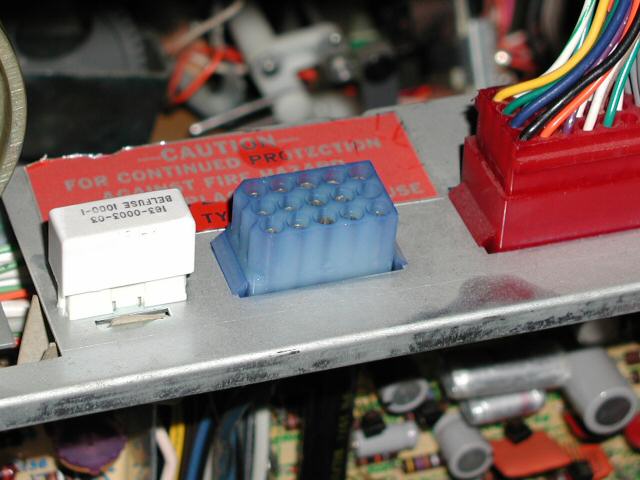 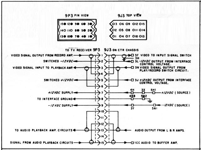
"9J3" THE BIG BLUE CONNECTOR ON THE FISH TANK This diagram is of the audio / video interface connector, 9J3. It is located on top of the fish tank, between the AC power fuse and one of the two transport connectors. The original diagram is a little bit complex, but that won't stop us. Connections are as follows:
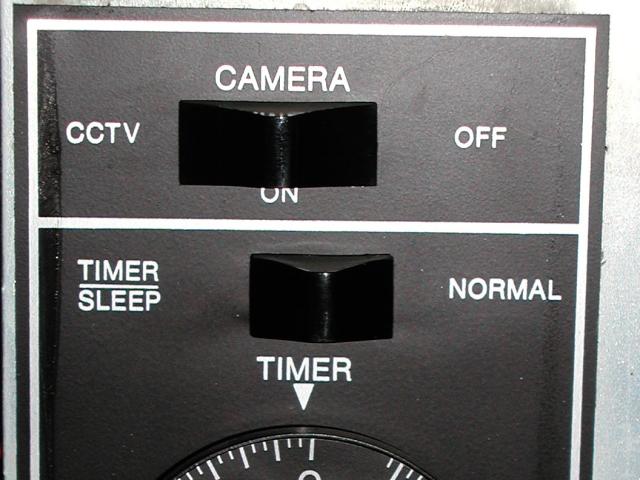
FRONT PANEL SELECTOR & TIMER SWITCHES The Cartrivision VCR can record from two sources. Either the the television receiver by way of connector 9J3 or through the input jacks on the rear of the fish tank. To record from the inputs on 9J3, the front panel SELECTOR SWITCH must be in the CCTV position and the TIMER SWITCH must be in the NORMAL position. The SELECTOR SWITCH center position chooses the CAMERA & MIC INPUT located on the fish tank. This SELECTOR SWITCH also serves as the master AC POWER switch. Placing the SELECTOR SWITCH in the far right position turns off all power to the VCR. I will research a source of the necessary Molex connectors and post that information here at a later time. Stay tuned! [HOME]......[PREVIOUS CARTRIVISION PAGE]......[VIDEO RECORDERS MUSEUM] Last updated: January 09, 2005 |