|
LabGuy's World: Tiny Triniscope TV Project
This project is dedicated to the memory of Richard C. Webb and the entire color television team at RCA in 1950. What they achieved, even considering the tremendous resources of the Radio Corporation of America, was world changing. We ride their wave to this day. 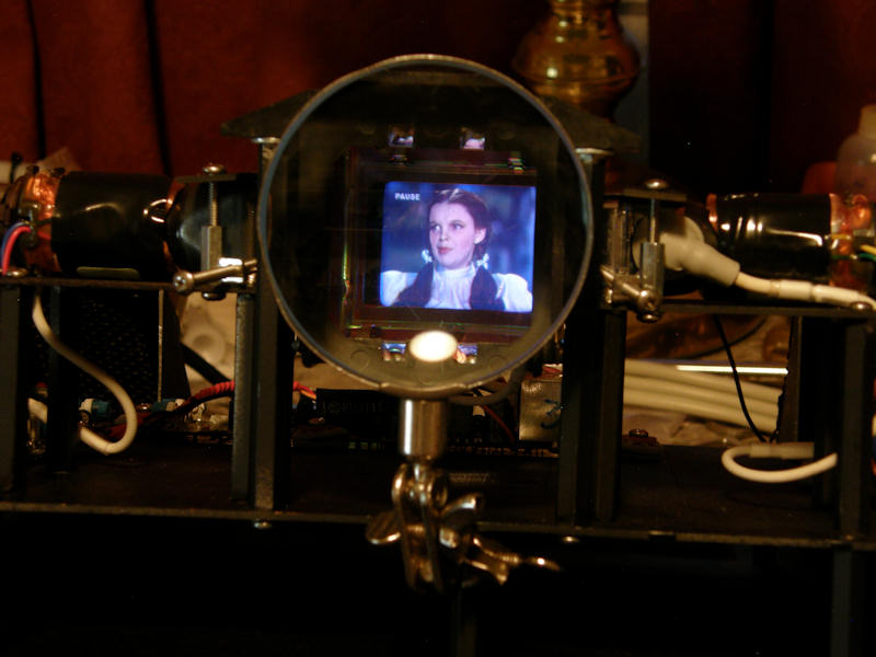
The Tiny Triniscope. A one inch, three tube, color television monitor - 20140412 PROJECT GOAL: Construct a color television monitor using three cathode ray tubes, or picture tubes in common terms, and the necessary optics. To overcome one of the biggest problems associated with triniscope monitors, shear volume, I chose one inch video camera viewfinders for my source of tiny monitors. These came from three unfortunate RCA CKC-020 "Small Wonder" color cameras from the 1980s. These picture tubes, and attached electronics, were absolutely perfect for use with this tri-chroic or "X" prism that I just purchased as surplus. It was originally used in an HD internal projection set. Three tiny LCD monitors and three high intensity color light sources drove the original television set. So, I removed the three HD LCD modules from my prism block and replaced them with the little picture tubes! You watch this TV by looking directly into the prism. The three tube faces will appear superimposed as one. Using these miniaturized components together, keeps the size of my triniscope manageable. 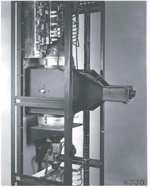
The first triniscope at RCA in 1950 - 20140327 Photo credit: Tele-Visionaries by Richard C. Webb. At RCA in 1948, Richard Webb and team's triniscope used three ten inch CRTs with appropriate phosphors and color filters. They were arranged in a T configuration around four dichroic mirrors arranged in an "X" formation. My triniscope differs only in that it lies horizontally and the RCA set was oriented vertically. To a viewer looking in, all three CRT screens were perfectly superimposed and appear as one. This early design suffered from a line where the physical mirrors necessarily had to meet at the center. In my modern prism, you can see this line only if you rotate the prism 90 degrees. I suspect the designer has used polarizers to good effect, eliminating or masking the center line artifact. The RCA triniscopes were reputed to produce excellent color pictures. 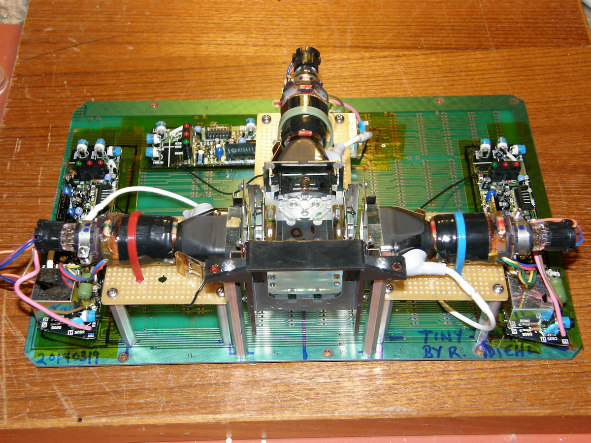
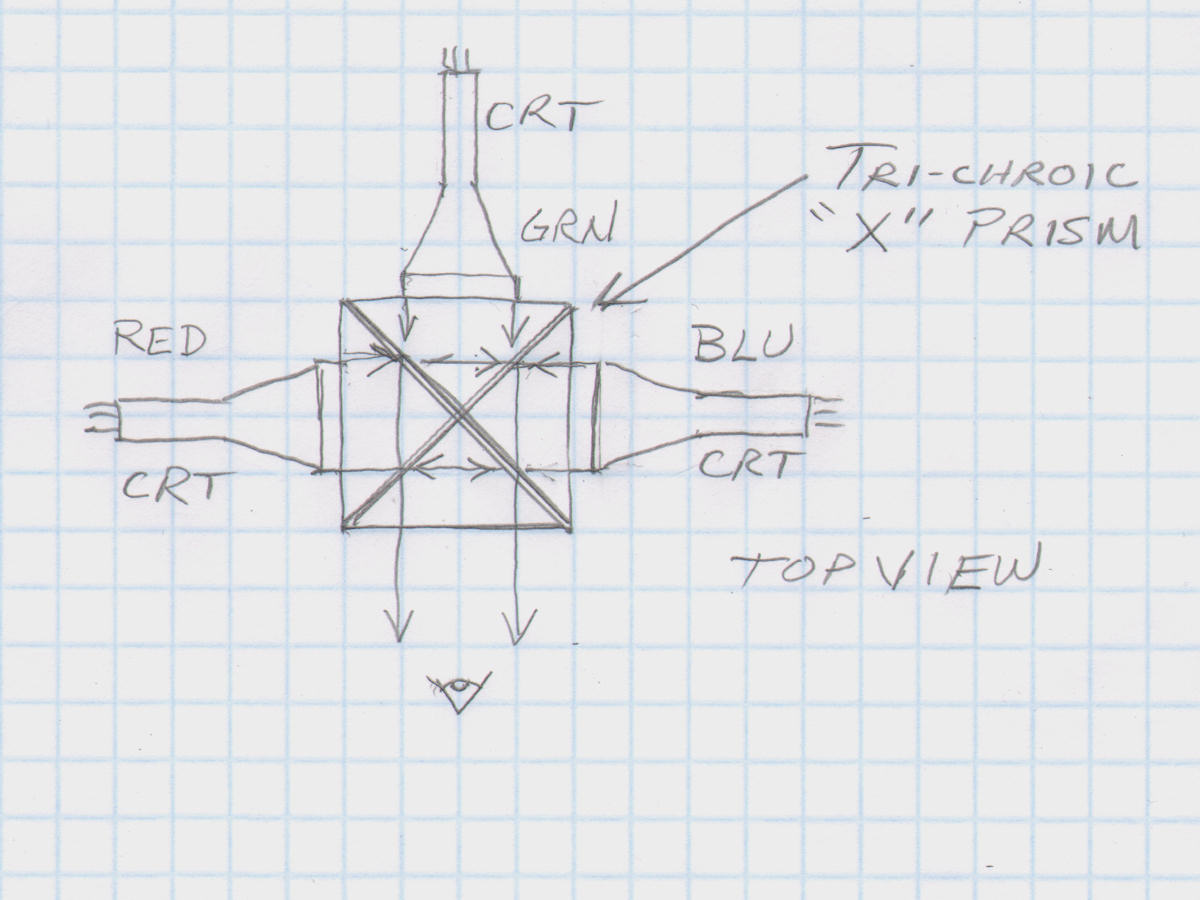
Early construction and the triniscope process - 20140328 In my simple illustration, above, we are looking down on the three tubes and the prism from the top. The primary prism is made of four smaller prisms. The sides facing the red tube at 45 degrees, are treated with a coating that reflects only red light and passes all other colors. Likewise, the sides facing the blue tube are treated to reflect only blue light. To enhance the color separation, an appropriate color gel of the proper color and density was placed over the face of each picture tube. This filters the normally "white" B&W screens to the appropriate primary color. By carefully positoning the three tubes to the prism, it is possible to overlap all three images almost perfectly. This will produce a full color image with no shadow mask or dot pattern artifacts. Triniscopes actually look film like. You have already seen this if you have watched any projected color television. My modern prism was purchased from Electronics Goldmine, an on line surplus store. In my opinion, one of the best surplus store web sites I have seen. Lots of unusual items. Especially geiger counters! I have never seen a geiger counter kit, ever, before visiting [Electronics Goldmine]. They have a half dozen! This projection television prism is [item number G19187]. Cheap at $25, these are factory new units removed from the HDTV set projecton engine. As you can see, this made the Tiny Triniscope project possible. 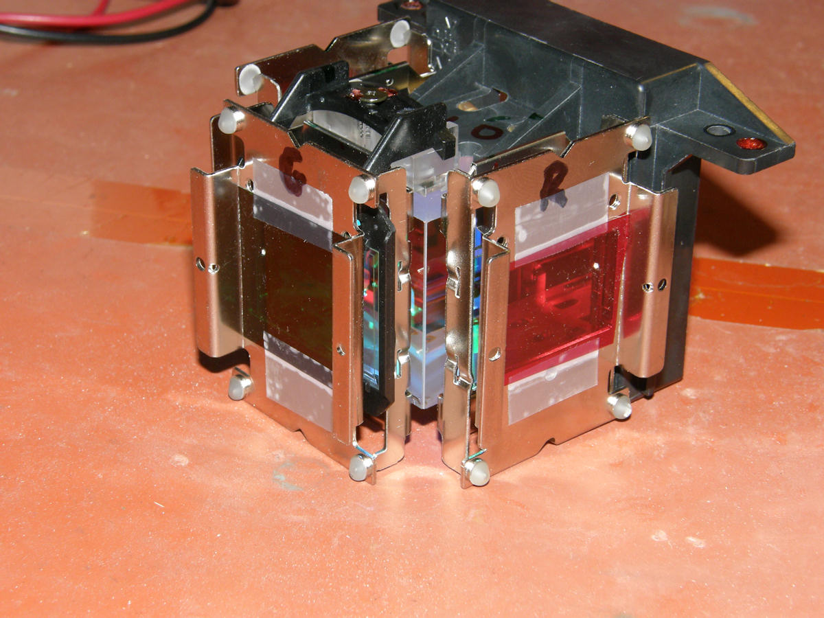

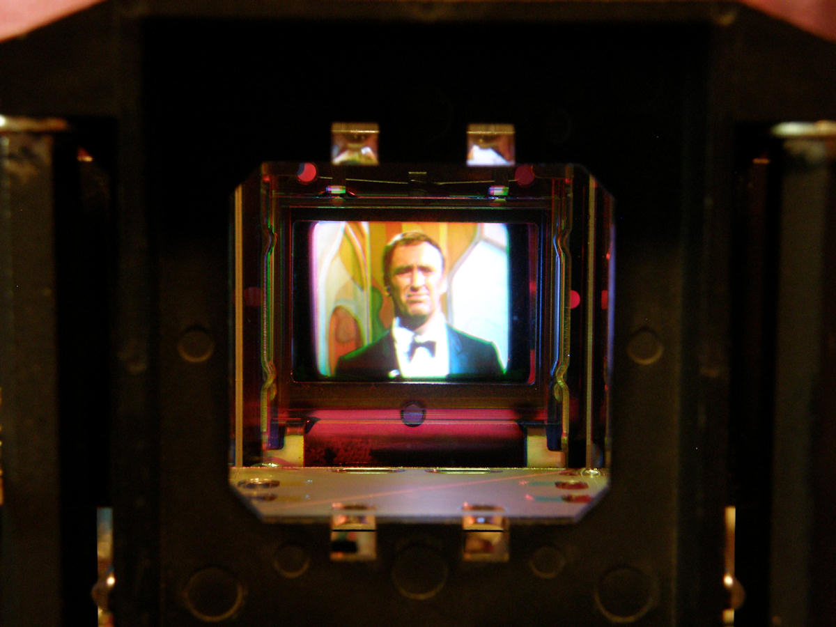
Two views of the prism input faces with color gels added - 20140315 This is a project I have imagined for over twenty years now. Use three viewfinder tubes to make a triniscope. Simple, right? Nope! Optics were always the show stopper. That problem is now solved! Above, we see the input faces of the prism. Three images are projected into the prism and the combined images emerge from the fourth port, shown below. Normally, this light is projected onto a screen. In this case the tubes are not bright enough for that. So, we will just look directly into the prism. You can clearly see the red, green and blue color filter gels are installed and ready for action! The color purity will now be extremely vivid, as you will see below. But, first... 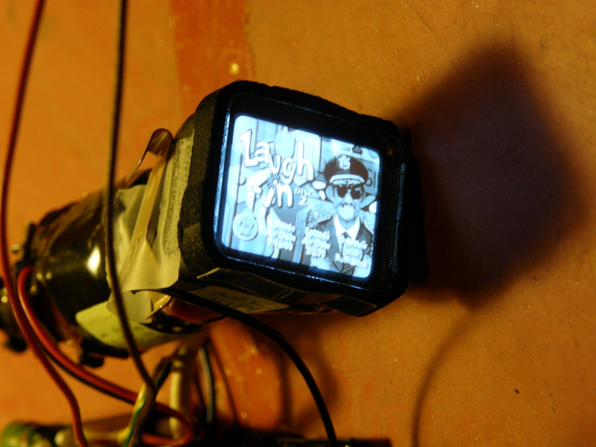
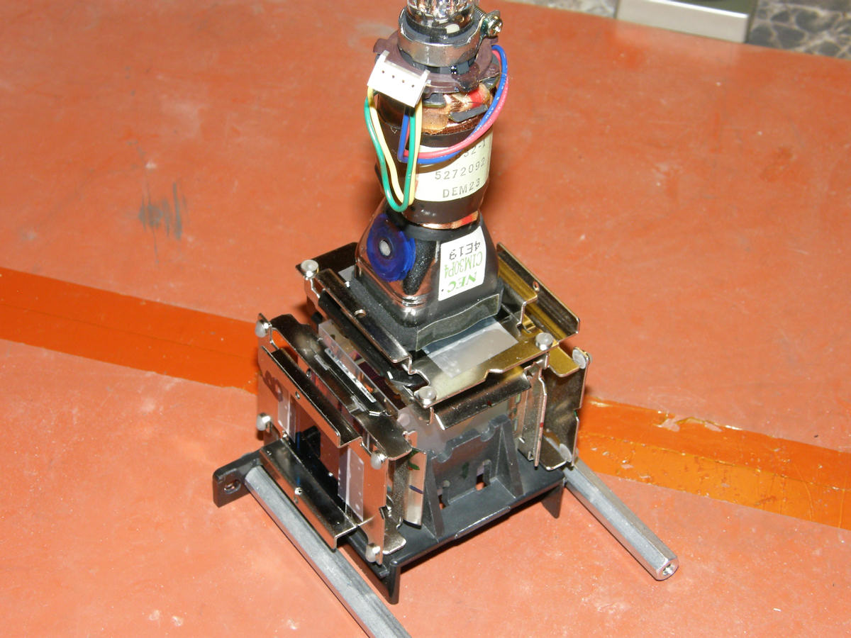
Tiny one inch picture tube working - 20140315 The NEC C1M30P4 CRTs fit the height of the LCD frame perfectly. The 4:3 aspect ratio of the tube is perfect because it has left and right wiggle room so I can align the three tube faces to each other optically before undertaking the geometric alignment of the pictures. The CRTs also have extremely flat faces and relatively precise dimensions, so it should be reasonably easy to physically align them. To keep this project as simple as possible and increase the chance of success, I am using complete video monitor sub assemblies. These modules are a complete black and white CRT video displays that operate on 12 volts DC and less than two watts of power. You can find these monitors in sizes ranging from 1/3 of an inch up to two inches. Most of them are easy to use. Some are embedded in the camera design and those can't be used this way. 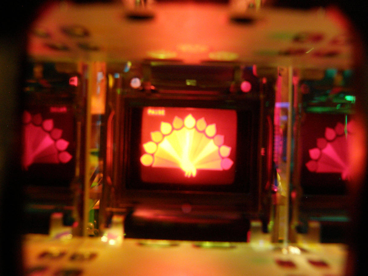
Testing each monitor individually - #1? Check! #2? Check! #3? Why so blue? - 20140315 Video will be sourced to this set initially from the YUV outputs on my DVD player. I will construct a matrix circuit to convert the YUV to RGB with sync to feed to each CRT monitor separately. In the photos above, each monitor is showing the same composite video from the DVD player. The horizontal deflection coils are reversed on the red and blue monitors because they are reflected in the prism's semi-mirrors. The green channel passes straight through the prism so it is left to scan normally. The yellow discoloration of the red channel is a malfunction of my digital camera. The image is actually blood red when viewed directly. 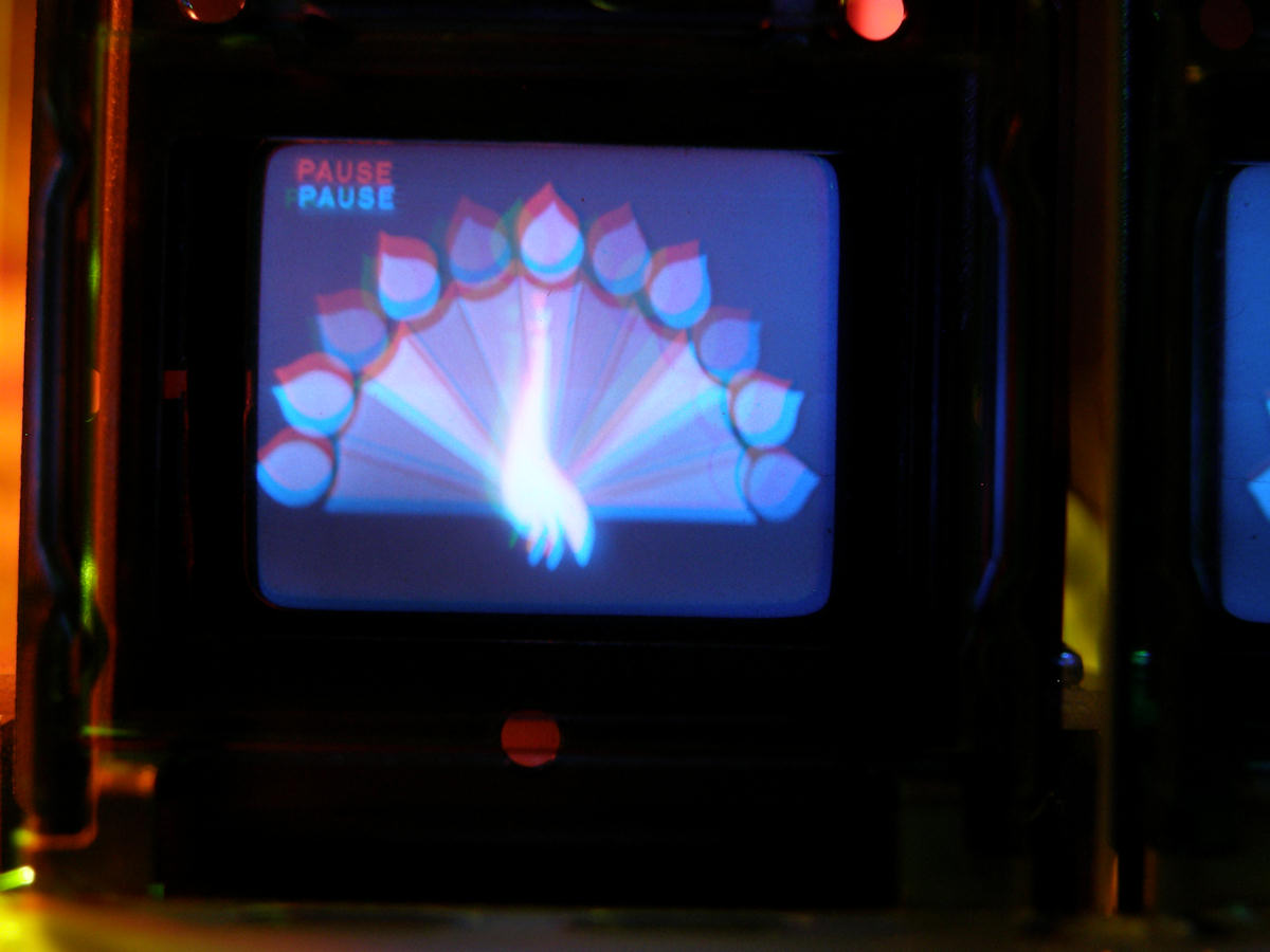
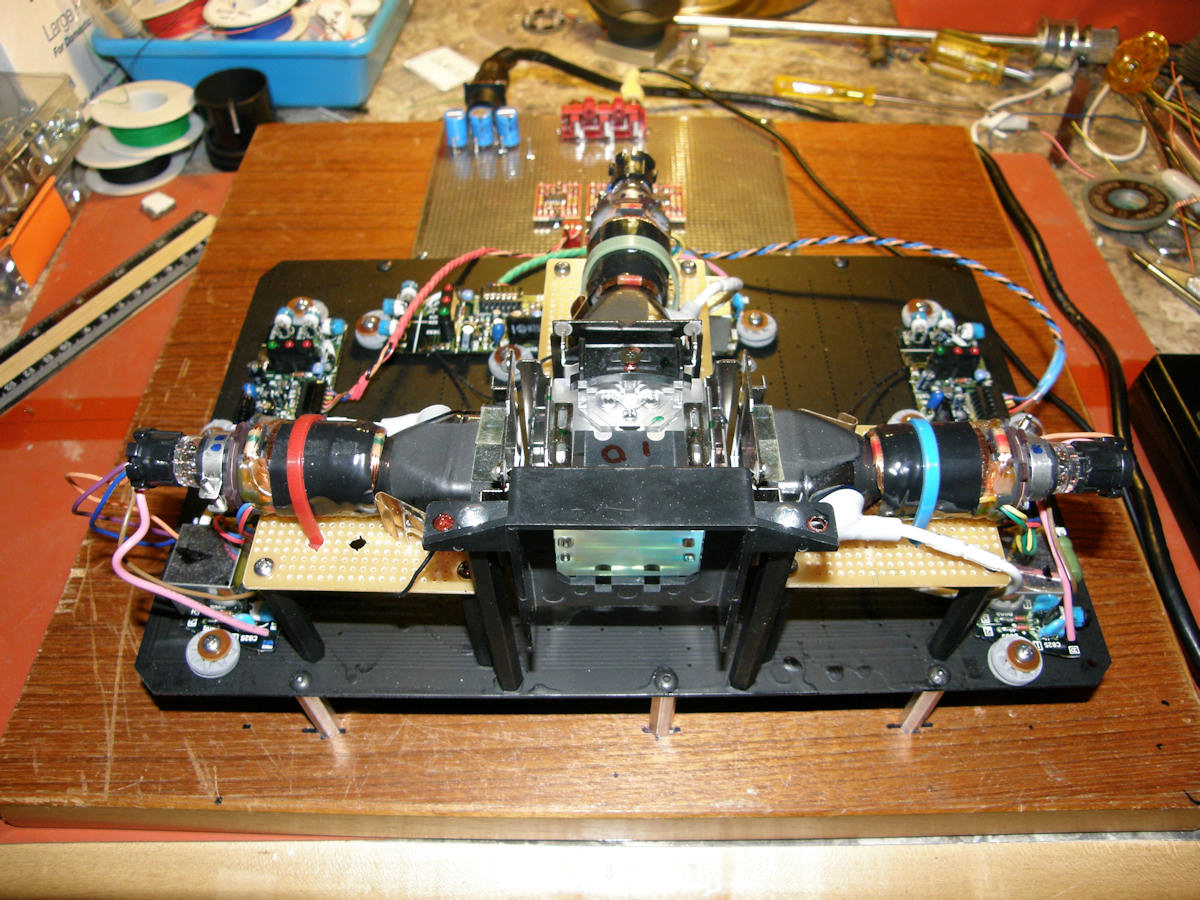
First light from all three monitors! 20140323 This weekend was very productive. Got around to painting the base board optical black. Sexy! Permanently fastened the display block and the matrix circuit board to the wooden base board. Obtained a suitable, ready to use, power supply. Installed the I/O connectors. Then, prewired the power connections to the video op amps on the matrix board. That's the silver board in the background. When this photo was taken, a single video input was being buffered and fed to all three monitors in parallel. This should produce a B&W picture, if everything were perfectly adjusted. The moment arrived. I powered all three CRTs together for the first time. As you can clearly see, the results were very encouraging. This test finally answers the BIG question. How severe are the geometric distortions between these tiny monitors? Now we know and it does not look insurmountable. No further attempt has been made to adjust anything. Still, it's not bad progress for only one week of construction. Onward next to the rest of the color matrix circuit! 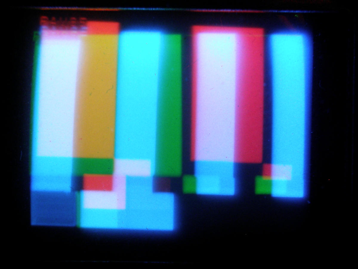
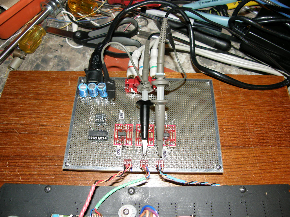
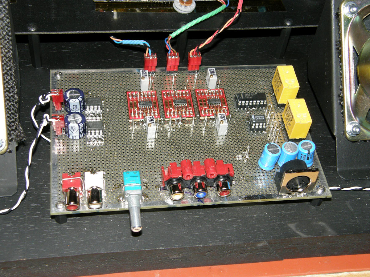
First color images and the matrix board! 20140326 Woo hoo! I completed the assembly and alignment of the color matrix board and sent true RGB video to the tiny TV monitors this evening. You can see the results above. Though the geometry will be a big challenge it appears the color matrix is working and making spectacular color. I designed an unnecessarily complex matrix with eleven op amps. Just because. The red circuit boards, on the larger board, contain the video amplifiers. The two other chips are an LM1881N sync separator and quad CMOS switch forming the active DC clamping ciuitry. I built in almost twenty test points to make debugging fast and simple. To read all about the YUV to RGB Color Matrix schematic and theory of operation [click here]. 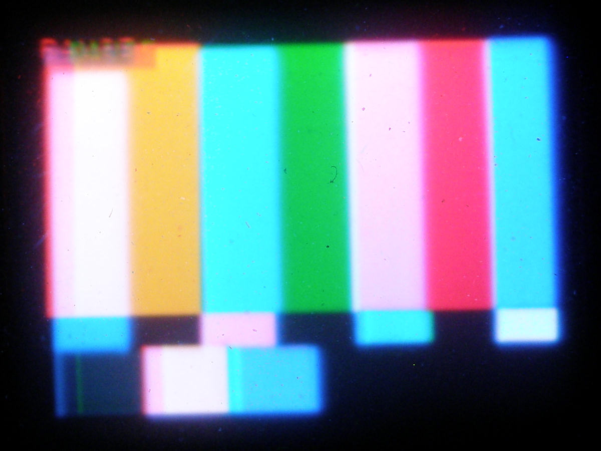
First attempt at image registration - 20140329 With assistance, I held the red and blue tubes in postion by hand while my friend snapped photos. Two dozen shots. My digital camera would never find really good focus. Though, it didn't seem to have trouble focusing on the dirty spots! This was the best of the batch. Eventually, the tubes will get precisely positioned and produce better pictures than this. Already, the Tiny Triniscope has been successful beyond my dreams. VIDEO: Tiny Triniscope on Youtube - 20140402 I made a short video and uploaded it to my Videolabguy channel on Youtube tonight. The first thirty seconds have no sound. This is intentional. It's quick and crude. You get to see Tiny Triniscope working in real time. Enjoy! 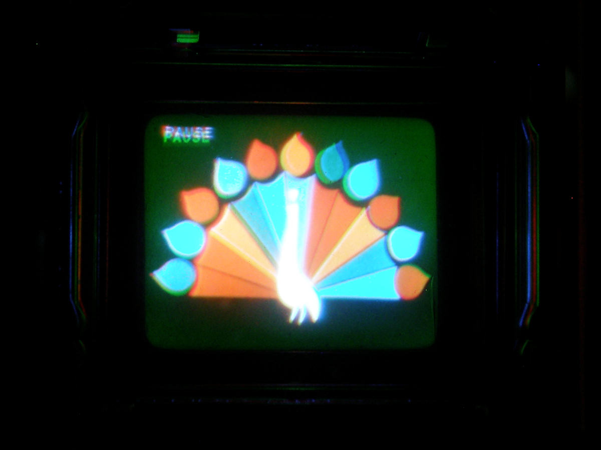
Some more attempts at image registration - 20140406 Just messin' around today. Trying various ideas. Things just get better and better on this triniscope. Finally got the green tube centered and solidly glued down. Above are a few examples of the preliminary results. To the unaided eye, these images appeared perfect. Obviously, I need new eyes! Still, the quality of the registration improves with each experiment. 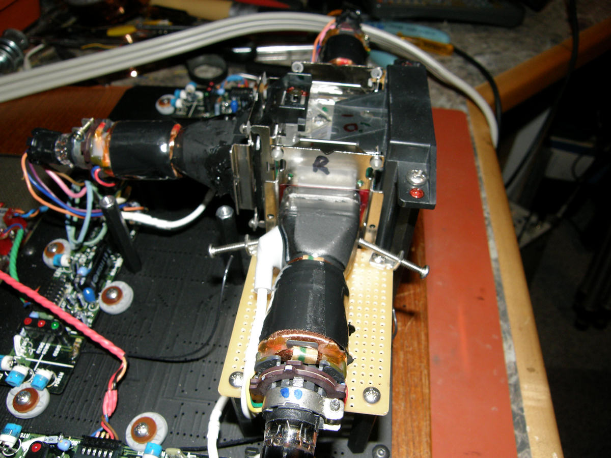
Simple left-right positioning screws - 20140406 Using some simple right angle brackets and screws gives me a primitive left-right positioner system. The results are already very good. Next phase will be to lift the tubes on some foam rubber tape, and add a small cross bar that allows me to adjust the height and tilt of the red and blue tubes. Another addition will be a simple rubber or elastic band to pull the tubes up against the prism. VIDEO: Tiny Triniscope with Improvements - 20140406 I made another short video today and uploaded it to my Youtube Videolabguy channel. Some of it looks awesome. Some, not so much. Enjoy! 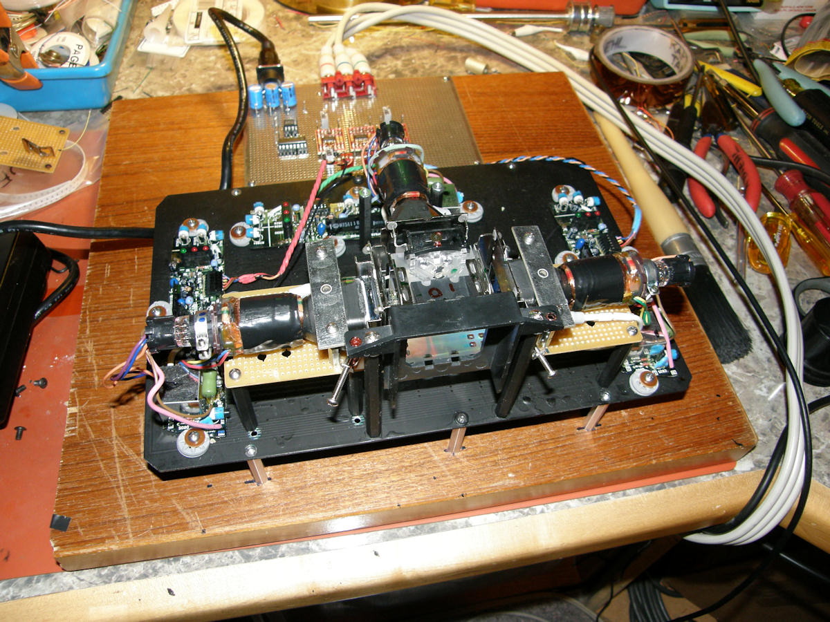
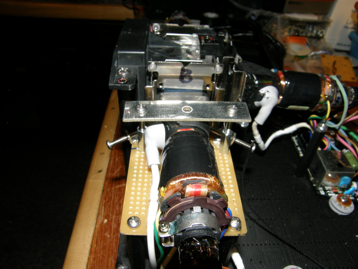
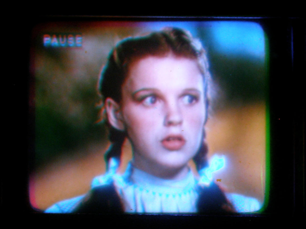
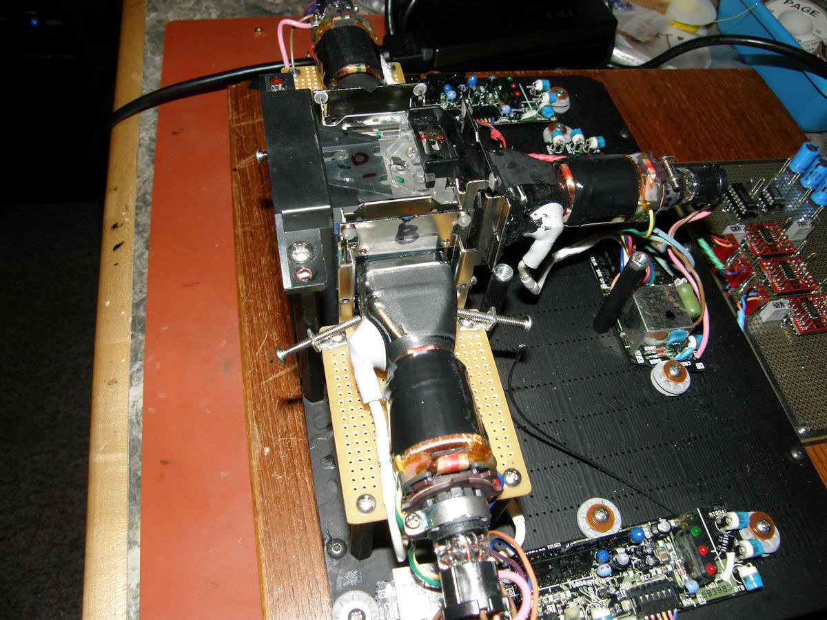
Tiny Triniscope is complete! - 20140407 That's it folks! She is done. The Tiny Triniscope is a functionally completed project tonight. I constructed the simplest positioners possible. The red and blue tubes are raised slightly on some foam tape. A bar across the top of the CRT allows the height (vert cent) to be set by turning both screws downward. This compresses the foam tape a little, allowing the CRT to move up or down. Tilt is corrected by turning one or the other screw only. Another two screws provide the left/right centering conrol. These can be seen as Frankenstein bolts sticking out the sides in the middle image. It takes about three minutes to tune the geometry from scratch and it holds its settings extremely well. The color balance has been set and the geometry aligned. Dorothy looks totally amazed in the final photo. For a one inch color TV, it sure works mighty fine. Yes indeed! VIDEO: Tiny Triniscope Functionally Completed - 20140411 The final video has bee posted to my [Videolabguy Channel] on Youtube tonight. I will give you the walk around tour of the construction and function of a 3 tube triniscope television. Completed refers to "functional" completeness. It still needs, paint, audio, off/on switch, etc. Today is the day that Tiny Triniscope works as planned. What a great feeling! ON GOING IMPROVEMENTS or "POLISHING THE APPLE" 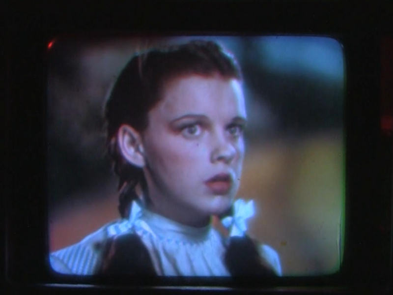
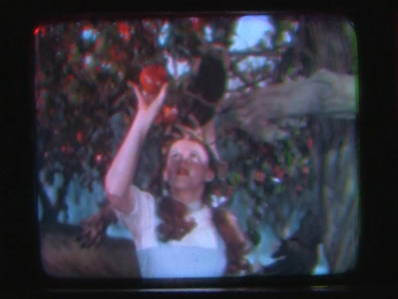
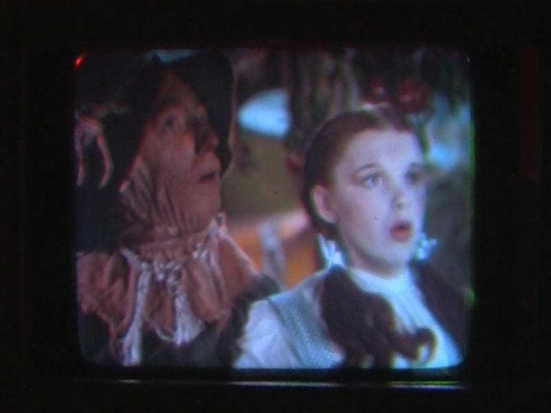
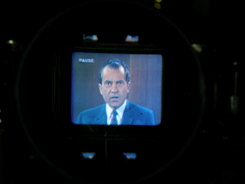
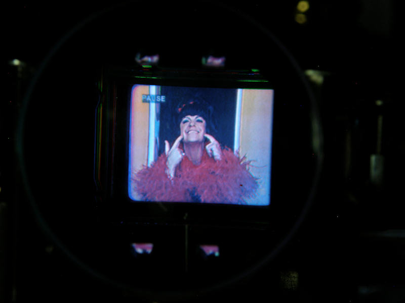
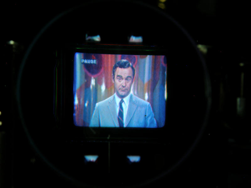
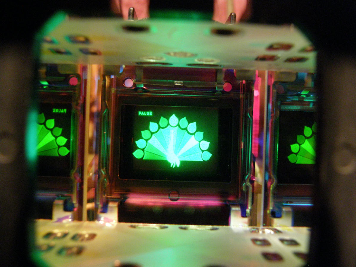
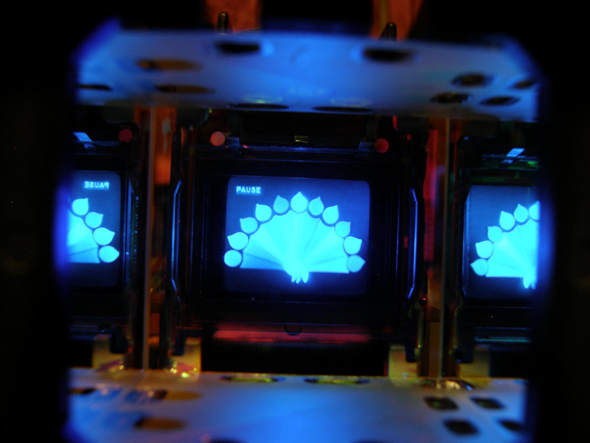
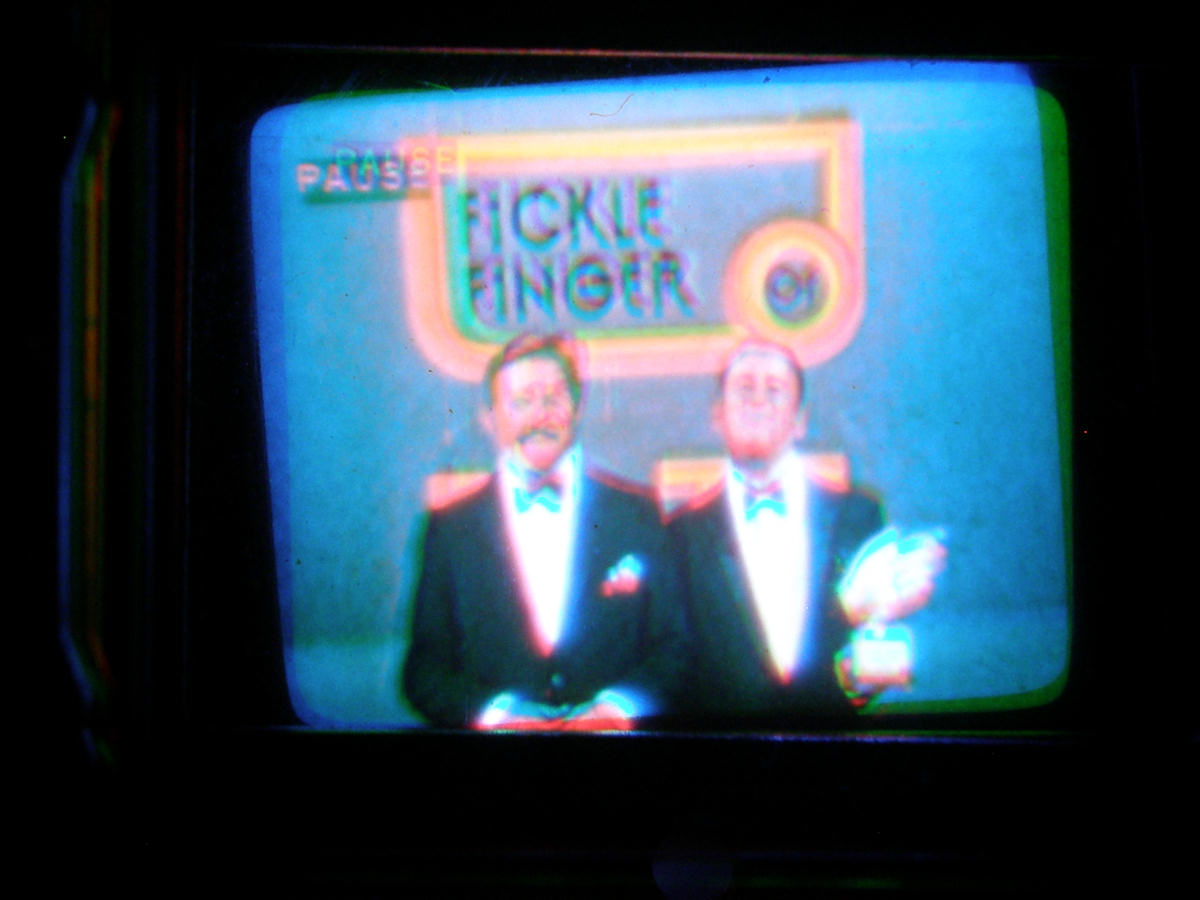
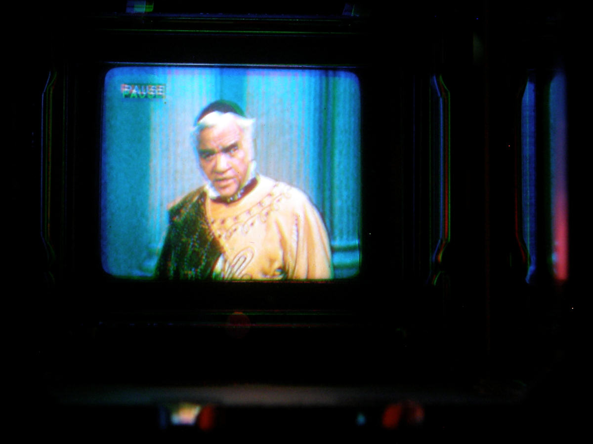
A sampler of one inch triniscope screen shots - 20140411 & 12 I was not satisfied with the bad photography in my first attempt yesterday. Today, I patiently set up my camera and spent several hours getting it right. Set the triniscope registration as precisely as I could. Photos one two and three were taken with my camcorder yesterday. Photos four through eight are taken with my digital still camera today, through the new magnifier lens in a darkened setting. The results are much better tonight. The quality of this little experimental TV is extraordinary! 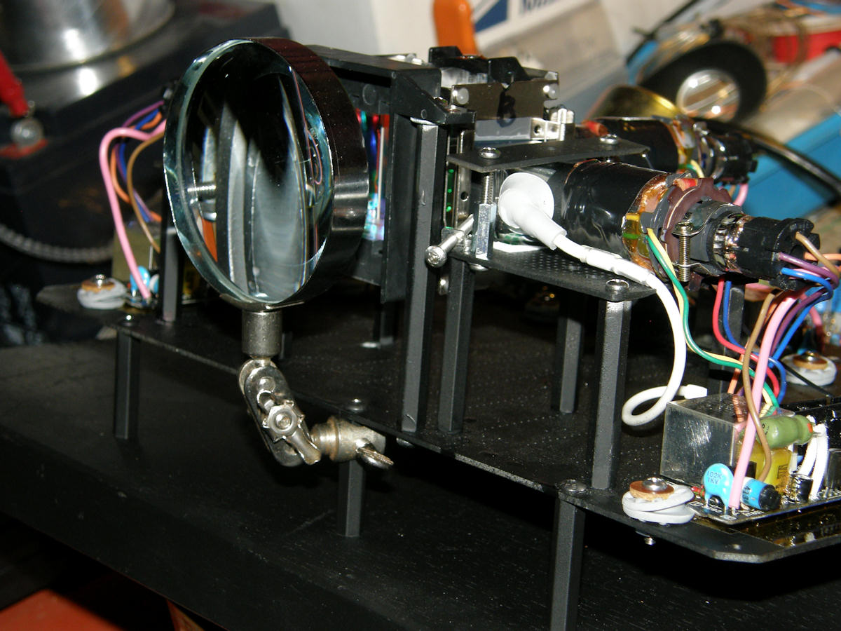
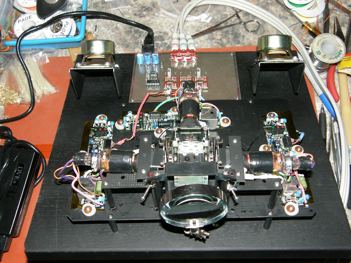
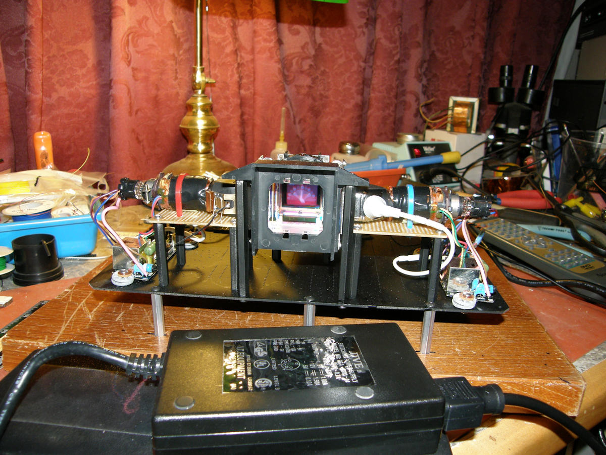
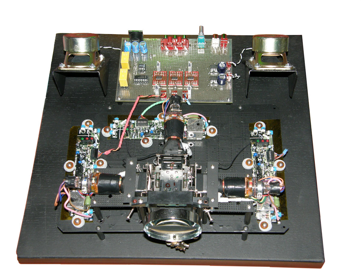
A magnifier lens, stereo speakers and some more paint. Looking great! - 20140412 Here in Silicon Valley this morning the big thing was the DeAnza College Electronics flea market. A real herd of nerds! What fun! I picked up several items that would prove to be of immediate benefit to the Tiny Triniscope. First find was a spiffy spy glass on a universal swiveling mount. Only Two fifty! After a really good cleaning, it conveniently attached to an existing support. The last photo shows how well it works. I'm tired of watching silent videos. So, next came a jim dandy pair of speakers with metal mounts. Free! Stereo audio amplifiers will be constructed tomorrow, though the actual IC chips won't be available before Monday. Also need a PCB mountable dual volume control with on/off switch and one or more small relays. Time to add an actual power switch to this TV.
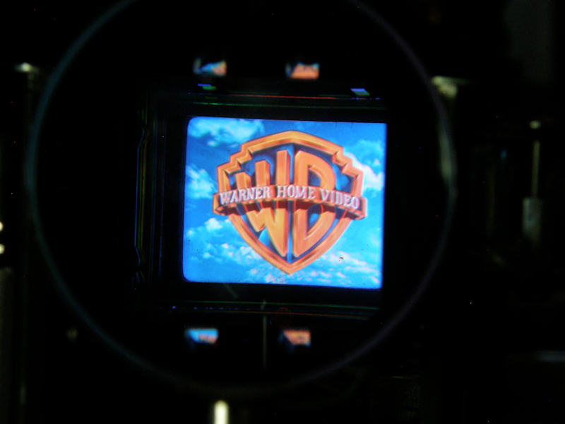
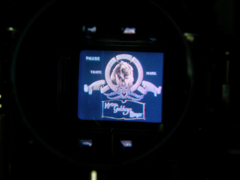
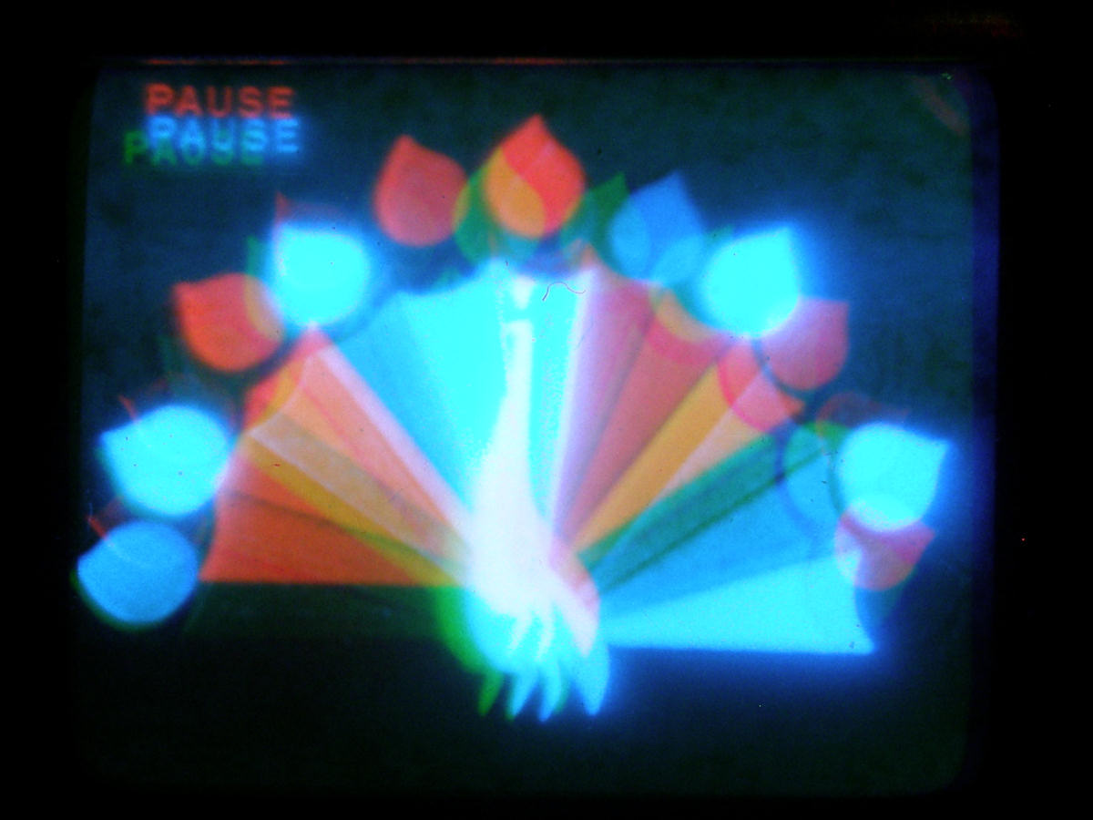
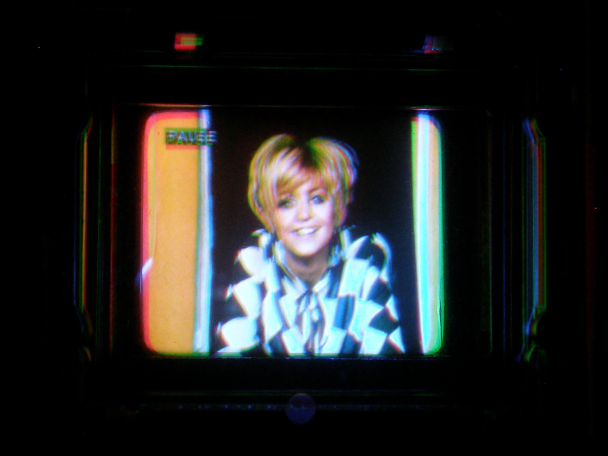
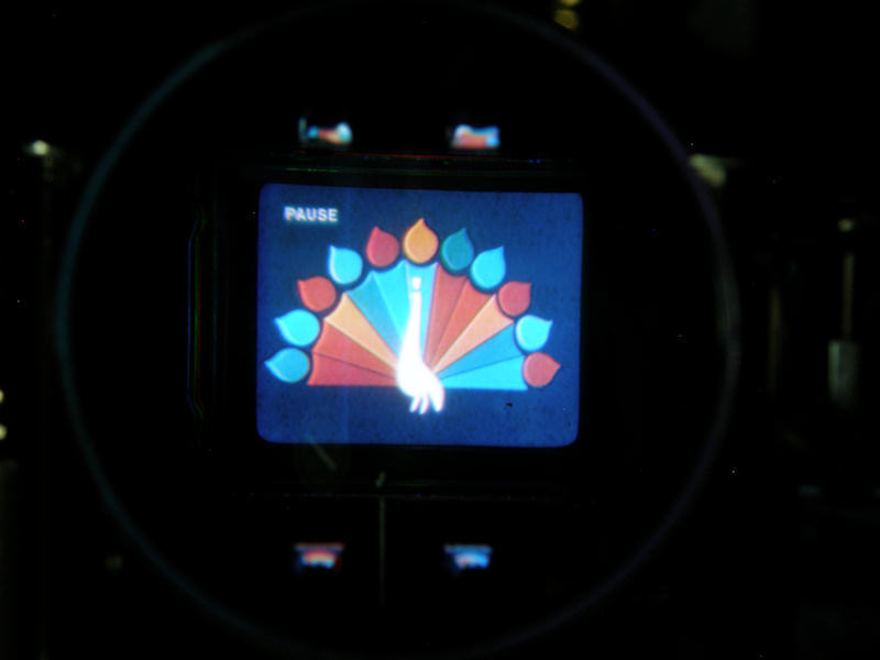
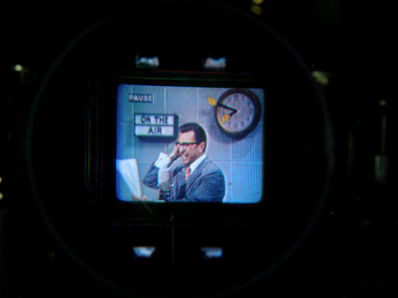
Miscellaneous corporate logos in near perfect registration! - 20140412 I dismantled the entire triniscope today to paint various parts and fix minor issues. Clean things up a bit. Like finally grounding the CRTs. Put it all back together and tested it. Still working. Then aligned it once again. How did it turn out? Check out the miscellaneous corporate logos above for yourself. Note how the word pause is extremely well registered in the upper left corner. The final photo is black and white with a sepia tint overlay. Did you know that any color display that can not make a good black and white picture will never make a good color picture? The most important alignment charts for both color displays and color cameras are monochrome. The triniscope looks great in black and white too. The NBC peacock appears so much on this page, it is only fair that I recommend the following site: [The Colorful Story Behind a Broadcasting Icon] - by Mike Clark. The story behind the most famous corporate logo in the world. 
Wrapping it all up - 20140422 Here is the Triniscope in its final glory. I've added two audio amplifiers and two speakers. There is also a pair of new yellow relays to provide a proper on/off switch. No more plugging and unpluging the AC power cord. What a gratifying project. It was a privilege to replicate this fine piece of television history. [HOME] [ELECTRONICS PROJECTS] Created: March 21, 2014 Last updated: November 11, 2015 |