|
LabGuy's World: Goldmark 1 - Making the color wheel
PART THREE: Will it go round in circles? Will it fly high like a bird up in the sky, Labguy? No. But, the color wheel did fly off the motor mount once during testing... 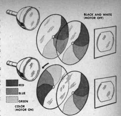
The original Goldmark two part color wheel design Dr. Goldmark was far more clever than your typical average inventor. Above, we see the 1949 color wheel as envisioned by the designer. This is a two part, split wheel, design which allowed the motor to be stopped and the two clear sections to align for viewing normal B&W broadcasts. There was a mechanism that assured that the clear sections would park prefectly in front of the CRT. When spinning, one section would swivel 180 degrees, placing color filters in all six positions on the wheel. Our wheel will never need to display B&W, so we will use a far simpler single piece color wheel design. 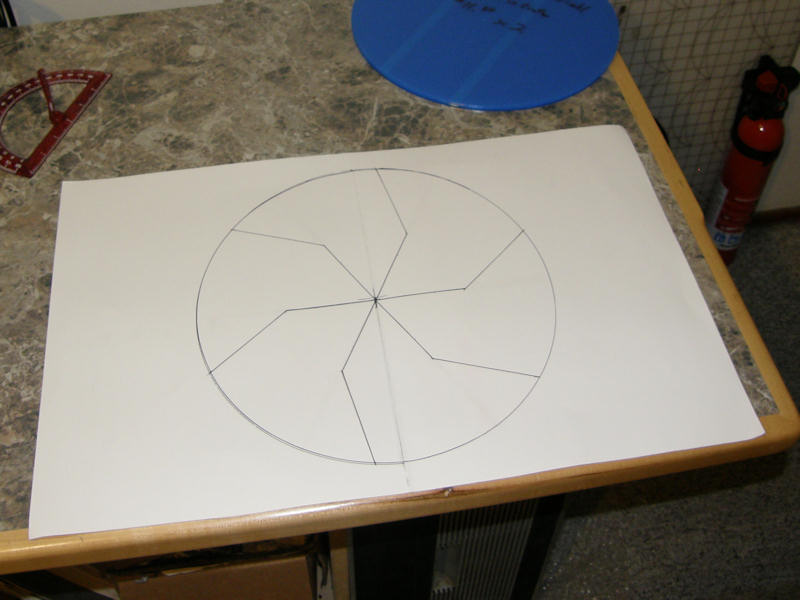
A template for a twelve inch CBS color wheel In the photo above, you see my drafted template, and round plastic sheets from TAP plastic (with the blue protective film). This is scaled for a 12 inch color wheel. You can also see the school child's protractor used to measure the angles and lengths. I did the arithmatic manually to scale this wheel from an image in a 1950s sicence magazine. As suggested by Cliff Benham, a CBS color TV guru of world renown, the following materials are best for constructing a practical color wheel used with a P4 phosphor CRT. These are made by Rosco for theatrical lighting use and come in large sheets approximately two feet square. The part numbers are: Rosco #25, #76 and #90. This is easily cut to patterns with regular scissors. This material was obtained at a local theatrical supply company for a very reasonable cost. [Roscolux - Color Filters Home Page] This will send your to the source. You're welcome! 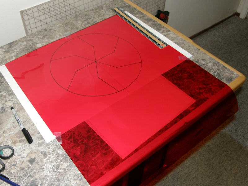
Overlay the template and trace the design to the material Time for grade school arts and crafts. We transfer the template to our red, green and blue gels and then cut out the chevrons. I used a black Sharpie pen to transfer the pattern to the plastic sheets. 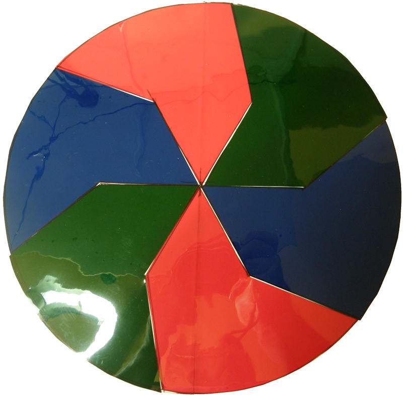
Six color chevrons ready to mount The size of the gels gave me enough final chevrons to make three 12 inch color wheels. Not that I plan to. I see my scissor skills are still in the third grade. No problem. As this is not critical nor is it visible while the wheel is rotating at 1440 RPM. In fact, I will mask over the gaps with black pin striping tape in the final assembly. 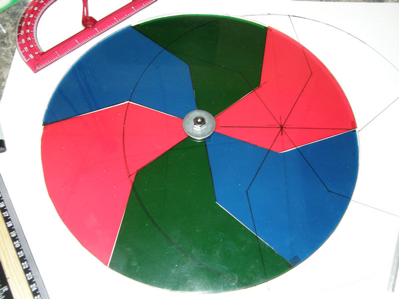
Color wheel constructed of two 1/8" thick 12" rounds of plastic from TAP plastics At this point, our color wheel is almost ready to use. Or so I thought. This wheel was constructed so poorly, it would never balance properly. The plastic product was of very poor quality and I had overlooked any form of practicle mount! So, this is what they call learning by doing... It sure is expensive! 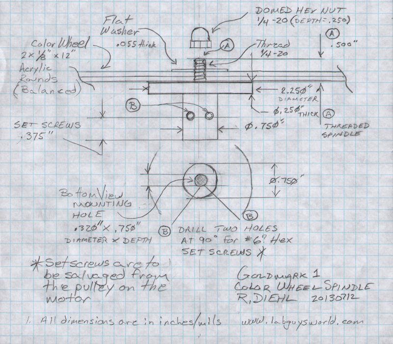
My Color wheel mount "engineering drawing" as submitted to [Good Plastics] Taking it up a notch, I contracted an industrial plastics company to manufacture enough materials for two complete new color wheels. The material, this time, was a very hard acrylic possessing excellent mechanical stability. In operation, this wheel experiences over 300 Gs of force at the outer rim! It must actually get larger, though minutely, when it is running at speed. The same plastics manufacturer was able to make two wheel mounts, that would attach the disks to the motors on hand. These were turned on a lathe from a high grade engineering plastic. [Good Plastics, Sunnyvale, California] - For all your plastics needs. Tell Jason that Labguy sent you. You're welcome, Jason! 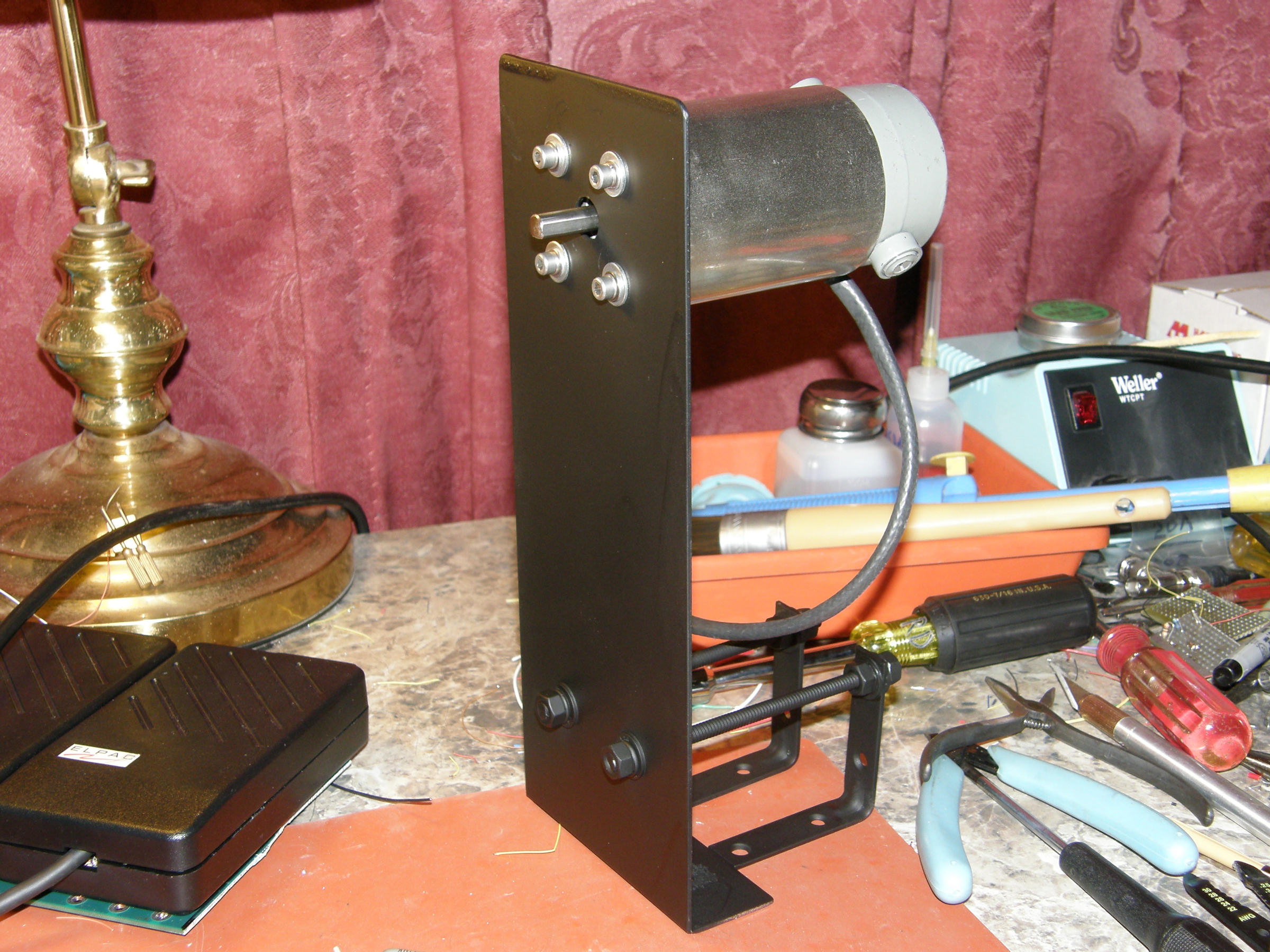
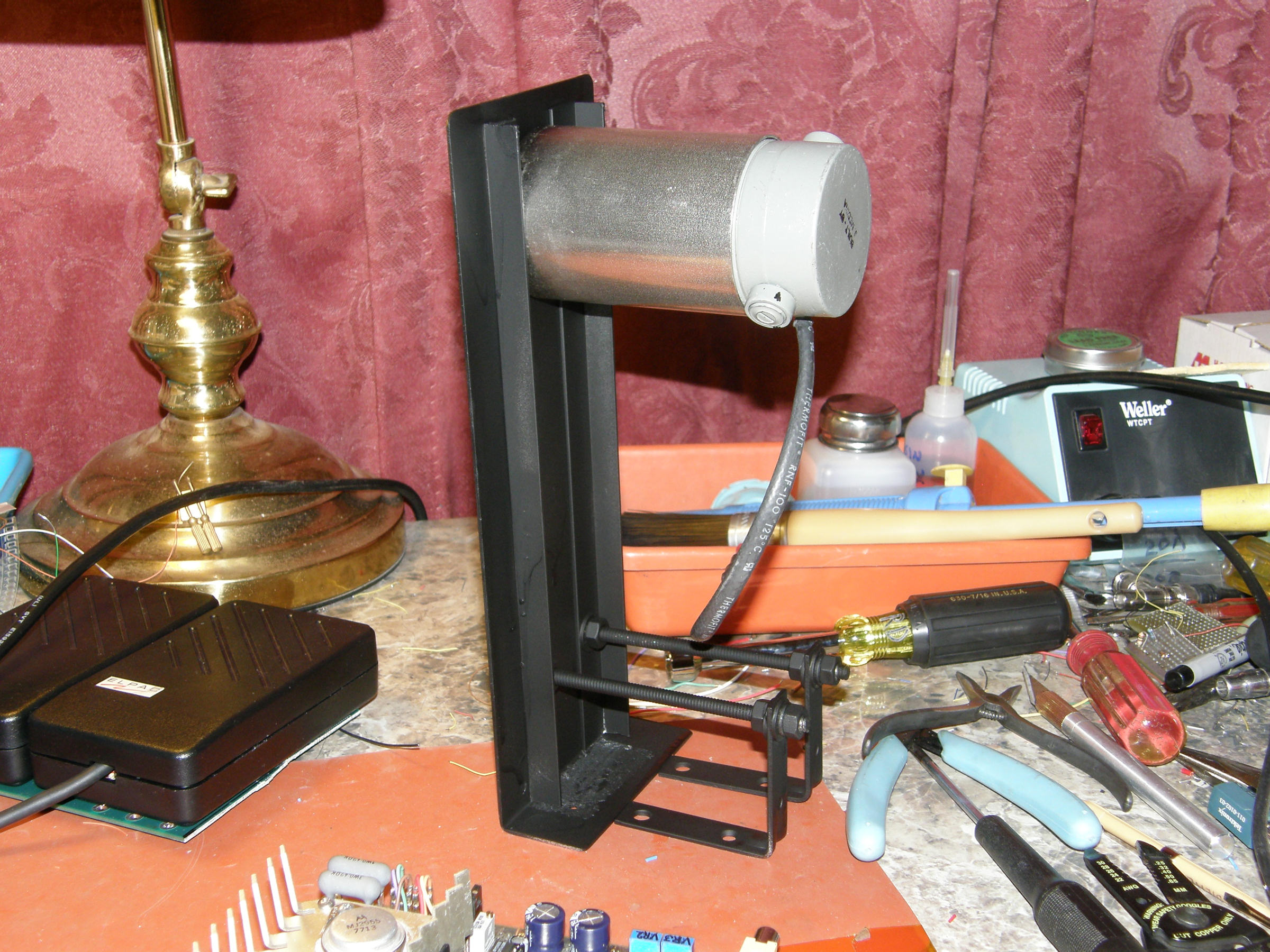
The color wheel and motor mount assembly This wheel and motor mount is mostly aluminum and some threaded steel rods. Nuts, bolts, washers and the likes. Painted flat black to make it non visible when operating. It is ready to receive the rotating components at this point. As you can see, this thing is made from bits and pieces that were on hand. 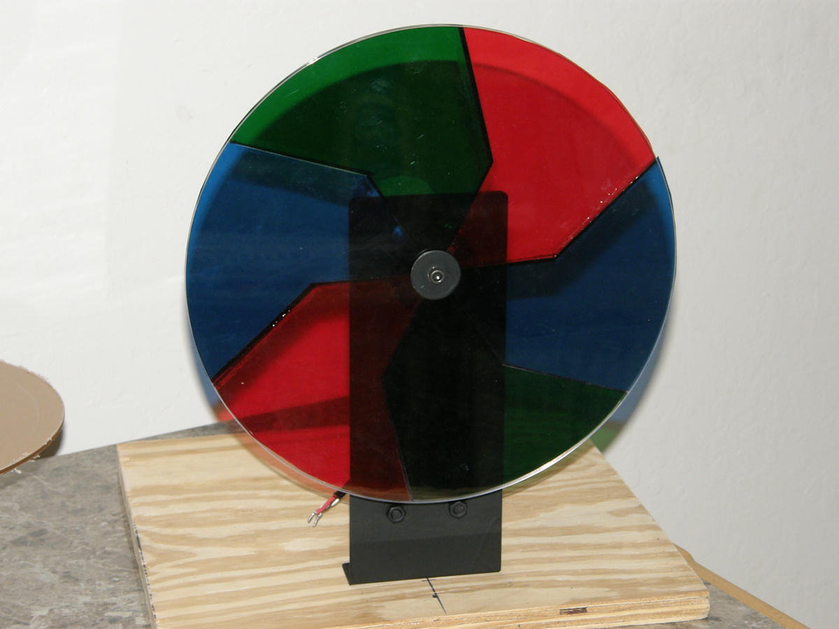
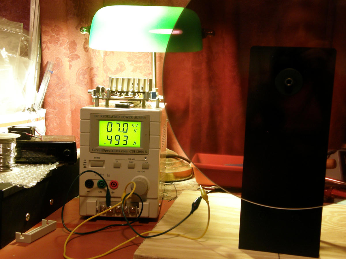
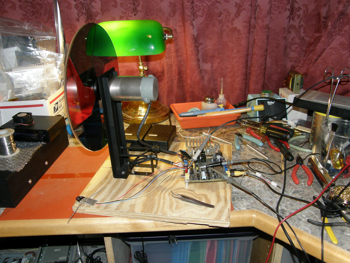
Color wheel and motor assembly mounted and undergoing testing Here is where all the bits came together. I glued color gels to the new machined acrylic wheel. This was then attached to the plastic mounting hub which attached the wheel to the motor. I bolted the motor mount to a wooden base. The wooden base is 3/4 inch plywood cut to 14 by 14 inches. This base sits on four non slip, rubber feet or bumpers as they are called. I temporarily powered up the photo sensor (more on that later) which produces a pulse each time the wheel completes one rotation. At 24 RPM, the pulse spacing is 41.67 milliseconds or one twentyfourth of a second. The pulse spacing is measured with the oscilloscope to set the running speed. The motor is being powered by a general purpose variable DC power supply. Next, I ran the test at speed to measure the power consumption. The result was 7 volts, at half an amp, which comes out to 3.5 watts of motor power. This information allowed me to move on to full testing of the servo system. 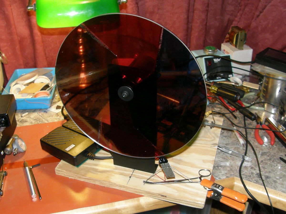
First fully loaded color wheel test - servo locked! I rigged a temporary mount for the photo sensor and fired it up. With a bit fiddling about, I was able to get a good once around pulse from the edge of the wheel. A slight adjustment of the motor free run speed setting to compensate for the load of the 0.555Kg plastic wheel and the servo actually locked up in sync with an actual CBS field sequential video signal! It wobbled for quite while, I must admit. But eventually it settled down and synchronized. The wheel is running in sync in this photo. The reddish hue of the spinning wheel is because it is the color profile that opposes the bluish profile of P4 TV phosphors. After the picture from a B&W CRT passes through this wheel, it will appear snow white, completely lacking the bluish tint of a B&W TV picture. (Did you ever notice that?) Last evening, while visiting with a friend, the question of how much force is on the wheel came up. A quick visit to [spincalc], an artificial gravity calculator site gave us the answer. It is usually used to design rotating structures in space. But, Hey! A "spinny" is a "spinny"! Am I right? So, according to spincalc, the forces on this wheel are as follows: Radius: 0.5 feet. RPMs 1,440. Rim Velocity 75.4 ft/S or 51.4 MPH. Centripedal accelleration 353.4 Gravities! Well, no wonder this wheel is a-misbehavin'! It is very wobbly at this point and will require some effort to get balanced. 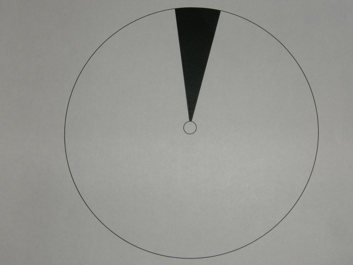
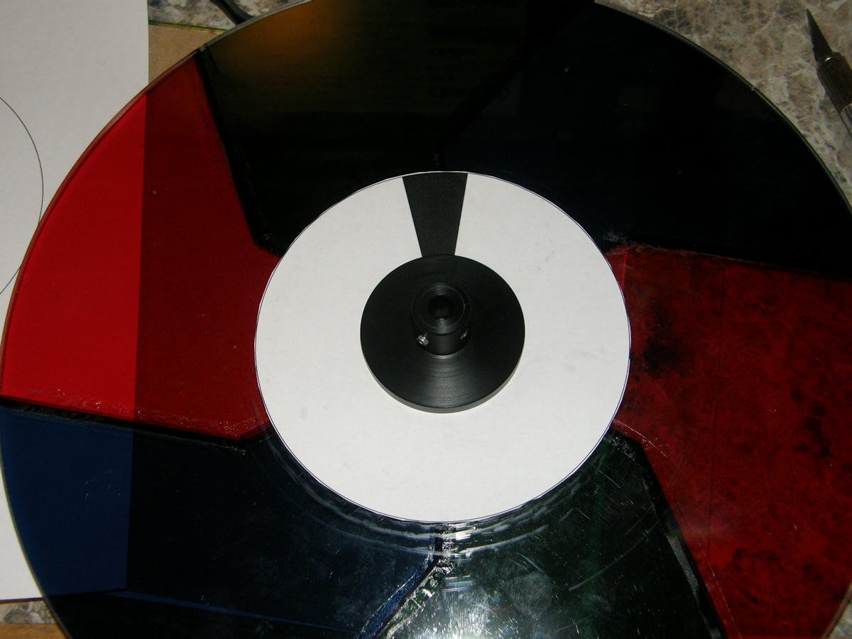
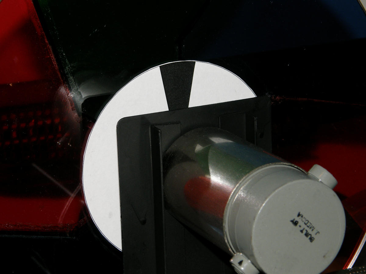
Laser printed tachometer feedback disk 20130805 For the tachometer disk, I laid out this simple pattern in pcb cad. Printed it on a laser printer. The toner has high contrast in the infrared and paper looks very bright in IR due to titanium oxide particles embedded within. The toner is carbon black and wax. That looks extremely black in the IR spectrum. I mounted the disk to the color wheel. Tacked the paper down with simple glue stick and reassembled same. 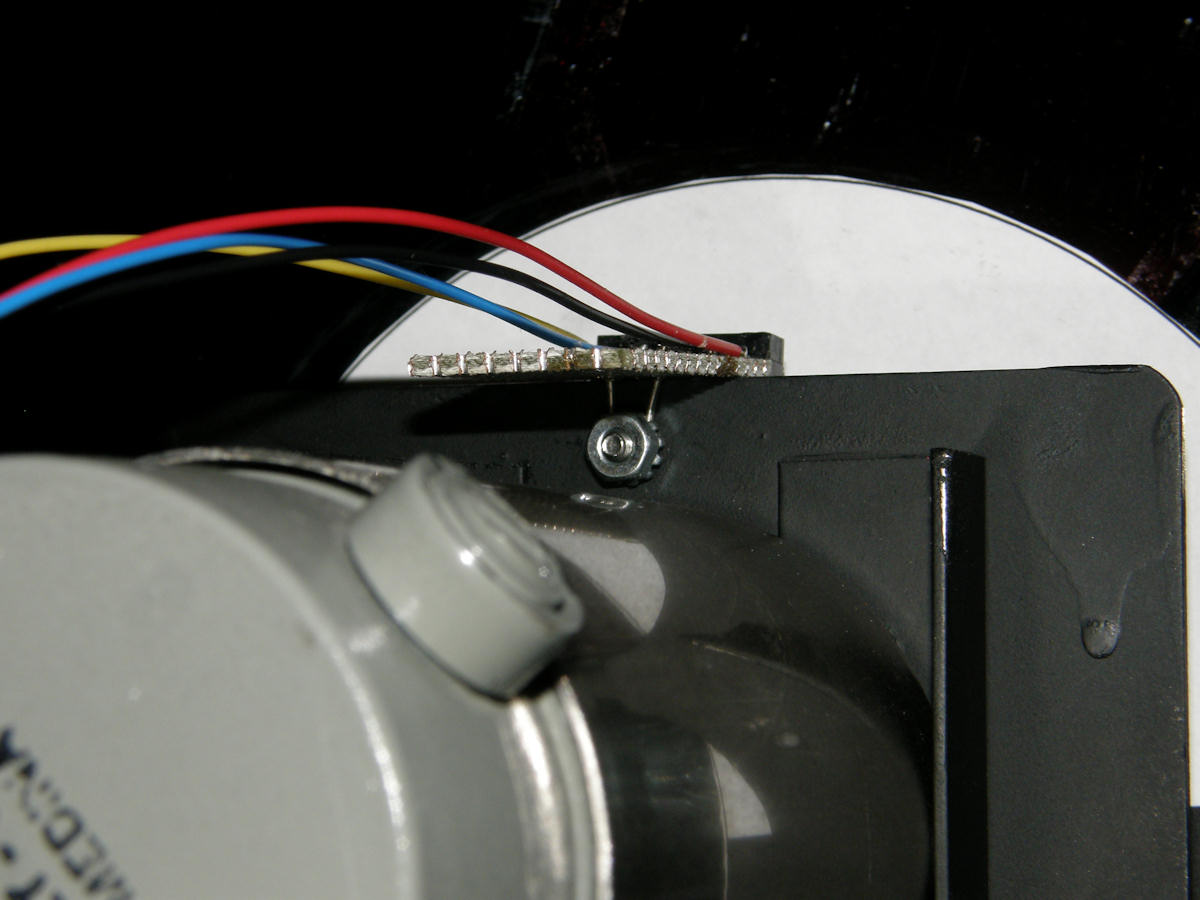
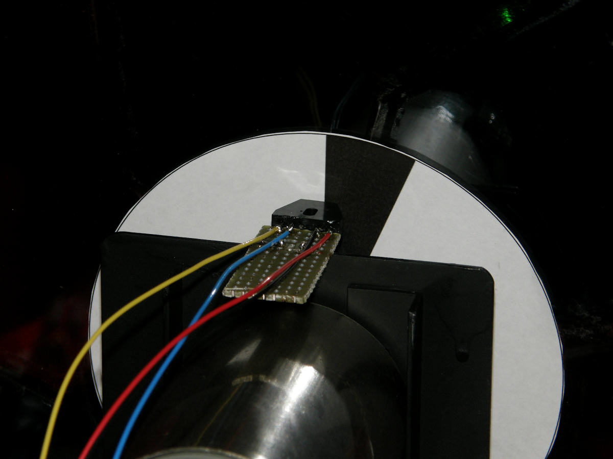
Laser printed tachometer feedback disk final test 20130818 The mounting of the photo sensor was simpler than I expected. I used a simple wire loop with a number 4 nut and screw to mount the small piece of vector board atop the motor mount plate. Spacing was perfect on the first try. The distance between the sensor and the tach disc is 150 mils on average. (The disc had a slight wobble.) Shot the second photo with a flash and just captured the tach wedge passing the sensor. 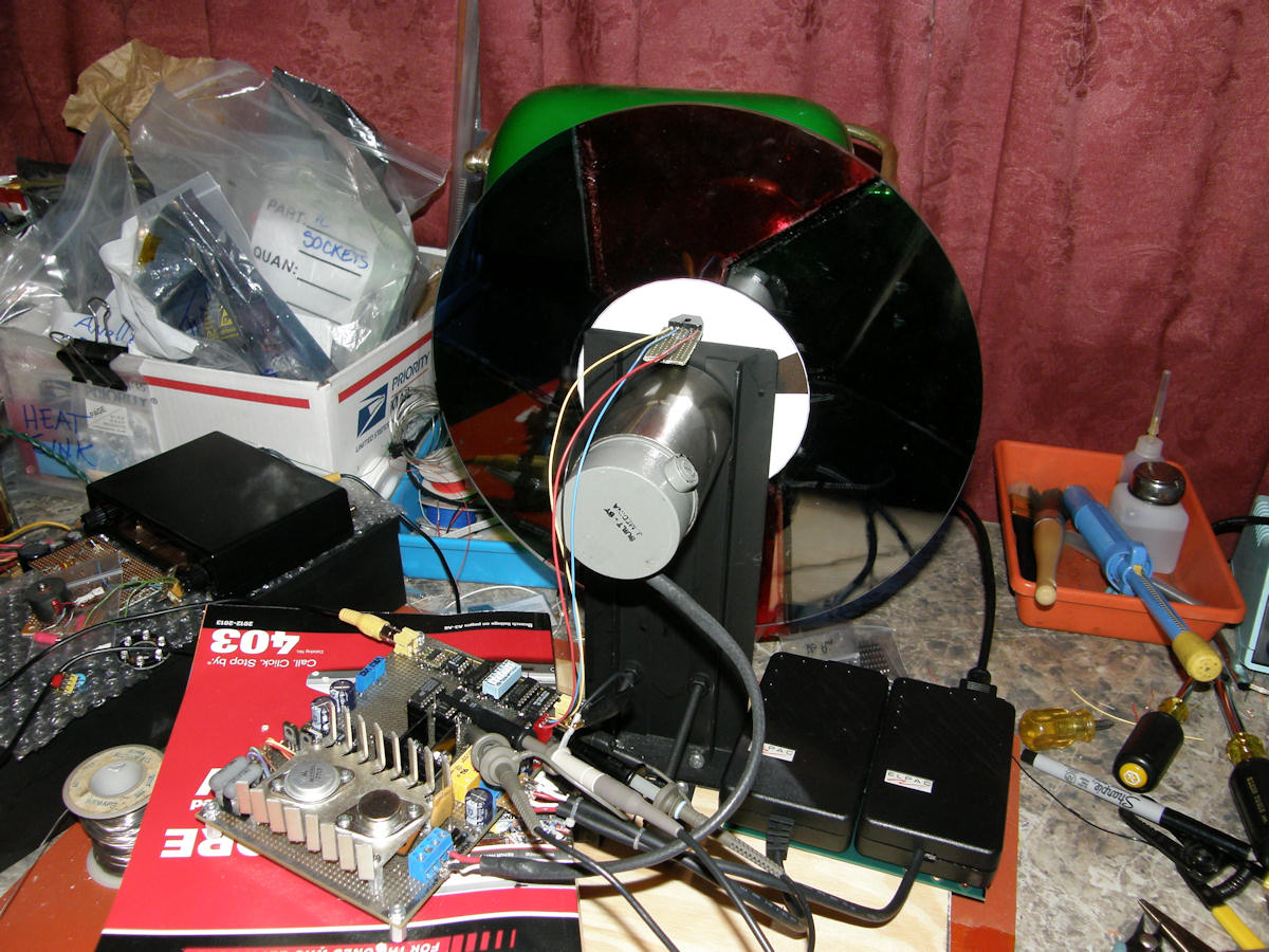
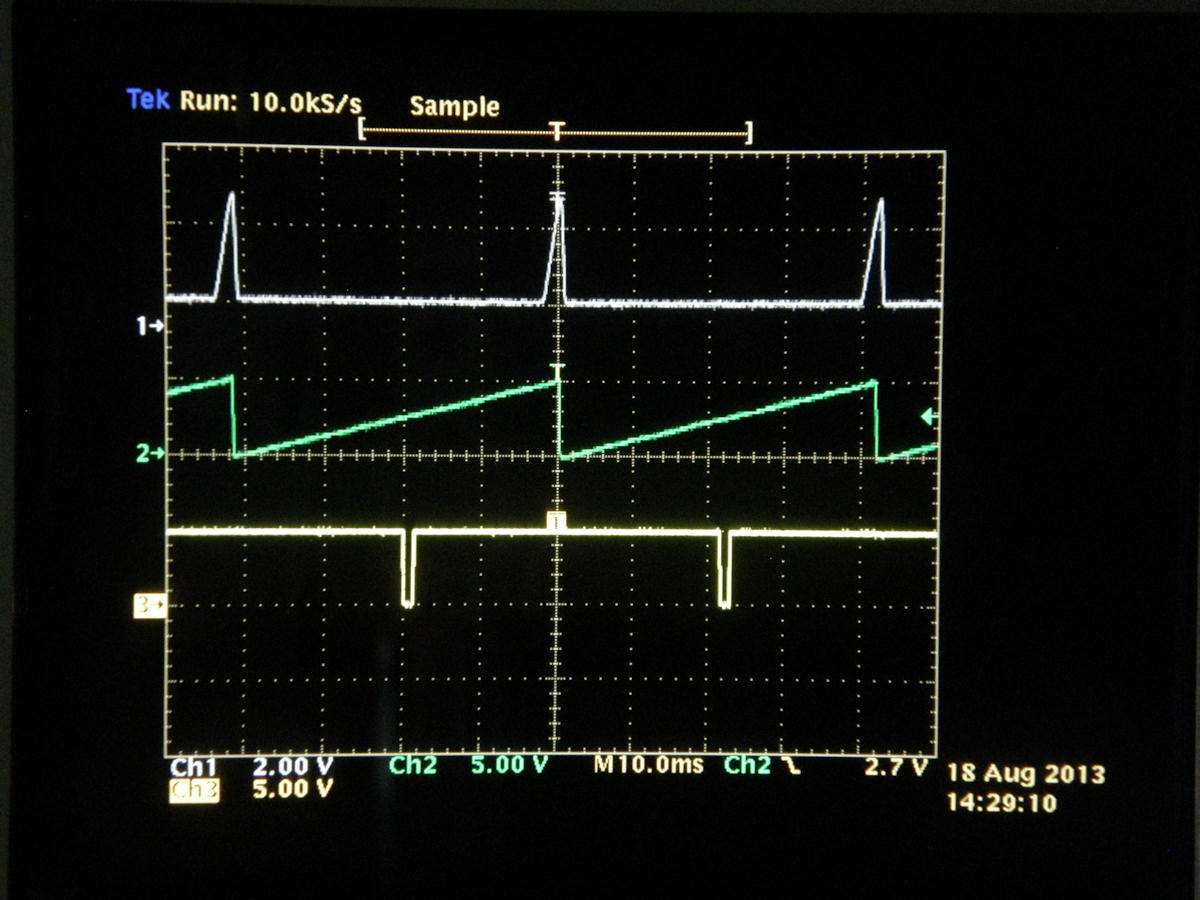
The laser printed carbon wax and snow white paper worked excellently with this photo sensor. We got a very good optical feedback pulse as seen on the top trace! In the first photo you see the test set up on my bench with the motor on and the color wheel spinning at speed. Trace 1. Direct output of the photo darlington transistor in the sensor assembly with the motor running at speed. A low voltage is present for white and high voltage for the black. More about that on the next page. Trace 2. Video generated twenty four hertz ramp waveform, which serves as our absolute time reference. Trace 3. Time delayed and reshaped tach pulse. The pulse we can move to adjust the wheel lock phase. Notice how the bottom two pulses are offset from the two pulses on trace 1. [HOME] [GOLDMARK 1, HOME] [GOLDMARK 1, SYSTEM THEORY OF OPS] Created: July 3, 2013, Last updated: February 24, 2014 |